
CUSTOMERS
We Work With Builders and Operators AlikeProcessMIX is trusted by software vendors and enterprises across industries - not just finance - to power logic, automation, and integration at scale.
Financial Institutions & Enterprises
Launch automation projects in a legacy-friendly infrastructure.Banks, fintechs, and enterprises use ProcessMIX to build internal systems for credit scoring, KYC, risk management, loan origination, collection, AML, marketing, eWallets, payments gateways and more.
Software Companies
Enhance your product. Accelerate integration.Software vendors use ProcessMIX to extend their platforms with powerful decisioning and automation capabilities - helping them integrate faster with their clients’ systems. ProcessMIX can be seamlessly integrated with legacy infrastructure to unlock modern functionality without disrupting what's already working.USE CASES
AI
Bring AI to Your InfrastructureWith the latest release, ProcessMIX puts machine learning fully under your control.
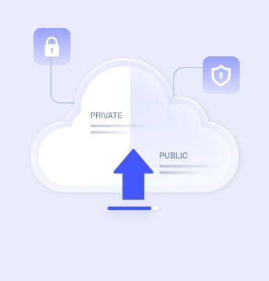
- Deploy and run industry-standard models entirely within your infrastructure — no data ever leaves your environment.
- Fine-tune models on your domain-specific data to boost relevance and accuracy.
- Integrate Retrieval-Augmented Generation (RAG) to enhance decisioning with real-time, context-aware insights.
With ProcessMIX you can to hostPrivate Gen AI
(Chat GPT like) with your own data.
(Chat GPT like) with your own data.
Full Data Sovereignty
Fine-Tuning Support
Built for Banking
RAG Ready
Seamless Integration
Get in touchLet's get to know each other better! Fill in the information about yourself to book a demo call with our manager.
First name*
Last name*
Email*
Company Name*
By submitting this form you accept our Terms and Privacy Policy*
Faster Launches, Faster ROIDeliver new products and internal projects in weeks - and see results sooner.
No-Code Agility for Business & Tech TeamsEmpower teams to build, adapt, and scale processes without relying on deep development resources.
Flexible Enough for Any ChallengeWhether you're modernizing legacy systems or building new offerings, ProcessMIX adapts to your strategy.
More Value from Every TeamReduce development cycles and increase output - all without growing your budget.
Contactsinfo@processmix.com
Copyright © 2025 ProcessMIX. All rights reserved